Features:
Introduction:
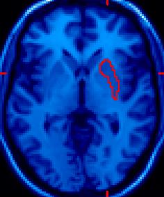 |
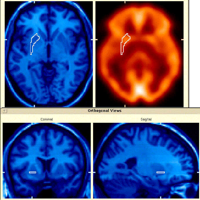
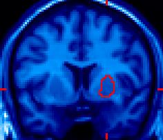
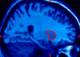
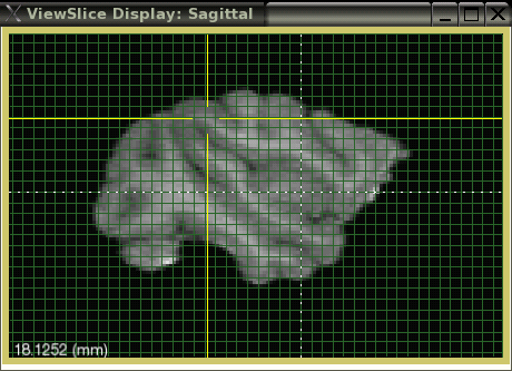
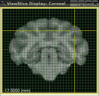
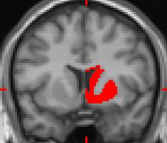
This triplet of images shows a Volume-of-Interest (VOI) drawn on the right putamen. All three orientations (axial, coronal, and sagittal) were used to refine the shape. Changes made to one image are immediately apparent in the other two views. There is no preferred orientation; all three orientations are treated equally. |
 |
 |
The basic BrainMaker consists of 3 orthogonal Views of slices through an image volume, a Main Menu, and a Mask Menu. Additional menus extend the basic functionality.
|
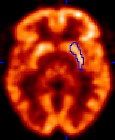 |
The images to the left show a ROI drawn on a MRI image and applied to (or overlaid on) a PET image. This is frequently done because MRI has better resolution than PET and also because the two modalities yield different information; MRI looks at anatomy or morphology, whereas PET examines a physiological process. The two modalities are complementary, and using information from the MRI data lets you accurately extract PET data from the desired anatomic location. |
BrainMaker Main Menu
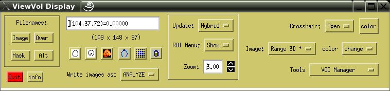
The picture above shows BrainMaker's compact Main Menu. Items are described from left to right. Really obvious items needing no explanation are... not explained.
Filenames: There are four (4) catagories that any image file can be slotted into.
All image files are read by clicking on the desired category and using the pop-up menu shown below:
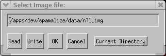
To browse for a file, click "Read". A standard browser appears. After accepting the filename in the browser, the image is actually read inot memory. For large images this may take a few seconds. After you regain control of the cursor, click "OK" to pass the image data into BrainMaker. You can select from a list of recently visited directories via "Current Directory".
Quit: Unceremoniously quits from BrainMaker. Any unsaved changes will be lost.
Info: Click this button to see summary information about the image data.
Info Box: Displays the data value and its coordinates for the pixel under the mouse cursor. The coordinates are 1-based (i.e. the image coordinates range from 1 to the image dimension). The image dimensions are displayed underneath the Info Box. When the cursor is passed over a button, a brief description of the button function appears in the Info Box.
A little-known secret: the Info Box is interactive! You can type in it to set certain parameters. Type "Help" or "?" to see the current options. Features include:
Hot Keys: There are several Hot Keys for BrainMaker. These work with linux and Mac, but not (so far) with Windows.
These hot keys will act upon whichever of the ViewSlice display windows is active. You may have to click inside the desired window with the middle mouse button to coerce it to become the active window.
Active View Buttons: Although you can draw on any of the 3 orthogonal views, only one view is ever considered "active". This is normally the one you are drawing on, or the view you drew upon most recently. For most operations the active view is irrelevant. However, occasionally it is important- these situations are discussed under the pertinent menu items. The active view is designated by the button shown in color (e.g., the axial view in the picture above). You can click on these buttons to force one of the views to be active. It is important to note that, although the buttons (and views) are designated as "axial", "coronal", and "sagittal", these are only labels- BrainMaker does not know (or care) if the labels are accurate. The labels are only correct for axially oriented images with the anterior region appearing at the top or bottom of the image.
Window Manager Settings: The operating system (OS) and the window manager settings you have set on your computer can influence how BrainMaker performs. This is particularly relevant for the Hot Keys, Active View buttons, and the Refresh button. For more details, see these Window Manager hints.
![]() Caliper Button: Permits precise measure of distance between two points. This button toggles between two states. The normal state lets you draw ROIs using the cursor, and the caliper is OFF. When the caliper is ON, it is highlighted in red. Click the mouse on a point on the image, hold the left mouse button down and drag to a second point, and release the button. A line will be drawn between the points and the length of the line (mm) is displayed.
Caliper Button: Permits precise measure of distance between two points. This button toggles between two states. The normal state lets you draw ROIs using the cursor, and the caliper is OFF. When the caliper is ON, it is highlighted in red. Click the mouse on a point on the image, hold the left mouse button down and drag to a second point, and release the button. A line will be drawn between the points and the length of the line (mm) is displayed.
![]() Grid Marker Button: Toggles grid marks off and on. The grid provides a handy set of reference lines for navigation, surgery planning, etc. The current location when you toggle the grid on is used as the reference point, with grid distances calculated from this point. Type "grid" in the Info Box to see current parameters. Type "?" in the Info Box to see how to change grid parameters. You can change the following parameters: grid spacing (mm), grid color, grid origin, lock/unlock the reference point. The lock/unlock featue is handy if you want to toggle the grid without resetting the origin. The grid spacing is specified in millimeters from the grid origin, and is accurate to within approximately 1/2 of a pixel distance. Any smaller than this and you are just splitting hairs. The grid origin is specified in terms of pixels (row, column, plane) and is 0-based instead of most similar BrainMaker parameters which are 1-based.
Grid Marker Button: Toggles grid marks off and on. The grid provides a handy set of reference lines for navigation, surgery planning, etc. The current location when you toggle the grid on is used as the reference point, with grid distances calculated from this point. Type "grid" in the Info Box to see current parameters. Type "?" in the Info Box to see how to change grid parameters. You can change the following parameters: grid spacing (mm), grid color, grid origin, lock/unlock the reference point. The lock/unlock featue is handy if you want to toggle the grid without resetting the origin. The grid spacing is specified in millimeters from the grid origin, and is accurate to within approximately 1/2 of a pixel distance. Any smaller than this and you are just splitting hairs. The grid origin is specified in terms of pixels (row, column, plane) and is 0-based instead of most similar BrainMaker parameters which are 1-based.
The image below shows an example of the grid overlay. The dotted line shows the grid "origin" or reference point, centered approximately on the anterior commissure. The curernt location was moved away from the AC by navigating with the middle mouse button. The current location is indicated by the yellow crosshairs.
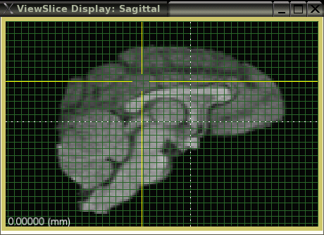
The following two images show views in other planes (lateral sagittal (left) and coronal (right). The distance of each image plane from the AC is shown in the lower left corner of the image. All other features of BrainMaker remain available when the grid is toggled on.
 |
 |
|
![]() Refresh: Updates all of the images in case something got out of sync. Unhides the ROI if you hid it by mistake. Also pops all Views to the front in case they got lost. Finally, frees up memory if pointers or objects have become orphaned. Like most refreshments, this is good for what ails you.
Refresh: Updates all of the images in case something got out of sync. Unhides the ROI if you hid it by mistake. Also pops all Views to the front in case they got lost. Finally, frees up memory if pointers or objects have become orphaned. Like most refreshments, this is good for what ails you.
Write images as: There are several options for image output: ANALYZE-7.5, AFNI, or EZZ. The default is ANALYZE, which is compatible with most other medical imaging programs. AFNI format is only available if you have AFNI installed on your system and designate the location in the defaults file. EZZ is a versatile file format that supports multiple dimensions, RGB, DTI, etc. All data written to an image file will be output in the selected format if available.
Update: Designates how images are updated. Options include:
Zoom: Increase or decrease the image display size. BrainMaker uses a set of rules to attempt to size the display for a nice balance between screen size and image size when it first reads in the image. After that you can change the size as you wish. The Zoom button changes the size of all images. You can type in any floating point number you want (hit "Return" when you finish typing!) or use the up/down arrows to change by increments of 1.0. Zoom=1.0 means that there is a 1-to-1 correspondence between image pixels and screen pixels.Values smaller than 1.0 shrink the image, larger values expand it.
This is a good spot to mention that BrainMaker does NOT take into account pixel size when it displays images. This means that if, for instance, the axial slices are 5.0 mm thick (Z pixel dimension), but the inplane (X- and Y-pixel dimensions) are 2.0 mm, the image will appear shrunken in the z-dimension. The only way to avoid this is to reslice the image to have cubic voxels, so the voxels themselves have the same dimension in all 3 dimensions. This is sometimes annoying, but is a conscious design decision to facilitate VOI fidelity.
Each of the individual Views can be zoomed individually by dragging one of the corners of the View to the desired size. (This has been known to fail under some opertaing systems.) The aspect ratio of the image array is always preserved.
Crosshair: Designates the type of crosshair shown. Pretty self-explanatory, except "Stub", which shows a small, stubby marker at the image edge. This is handy if want to know where you are within the volume but also want to see the entire image. The "Color" button to the right lets you select the crosshair color.
Image: Set various display parameters:. Asterisks denote default parameters.
The "Color" dropdown menu to the right of the Image dropdown menu lets you select a color table for the image (select "change"). Within the Color Table Menu, you can select from about 50 color schemes, and modify each table. Select "show" to show the color table underneath each image.
Tools: This dropdown menu provides a compact launching point for several important tools. The more important tools have their own section but are mentioned here:
BrainMaker Mask Menu
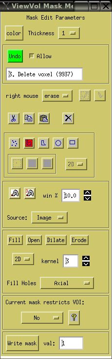
Mask Edit Parameters: Lets you change the color and size of the dots used to represent the mask. Currently, the only option for displaying the mask is as a field of small dots, Each pixel included in the mask has a single dot centered on it. Increasing the thickness makes the dots easier to see but obscures the underlying image.
Undo: Most VOI draw/erase actions are recorded, permitting you to undo up to 10 sequential actions. The action you took (Draw, Erase, etc.) and the number of affected voxels are displayed in the text-box. Since the affected voxels need to be stored in memory, certain actions which are potentially very large are excluded from Undo. Such actions include 3D volumetric search, Histogram searches, and morphometric operations. An alternative to Undo is simply to save a series of VOIs as you work, so you can revert to an earlier one if desired. If you run into memory problems, unchecking the "Allow" button will free up the memory required to store the undo operations.
Right Mouse Function: You can designate the functionality for the right mouse button. The default is to use it for erasing a VOI (the left mouse button is used to draw a VOI). You can also select "page", which leets you page through slices in a View by clicking with the left mouse. Clicking above the center of the image will page up (superiorly), clicking below the image center will page "down". The farther from the center you click, the more slices you will page through or "skip". For the record, the middle mouse button is always used to change the location (browse through the image volume) without drawing a VOI.
Draw/Erase buttons: When the right mouse is set up to page, the left mouse button performs double duty. You must explicitly designate whether you are drawing or erasing by clicking on the appropriate button. If you are in Draw mode, the Draw button (on left, shows a pencil with the drawing tip down) has a bright yellow background. In Erase mode the Erase button (on right, shows a pencil with the eraser down) has a bright yellow background. Note that the Draw/Erase functionality extends to some operations such as 3D search (see below)- if the last operation involved an Erase, the search will result in erasing all of the voxels identified. This can be handt to erase voxels but can be confusing the first time you forgot to turn on Draw when you were trying to add voxels to the mask.
On linux/unix/Mac, you can page through the currently activeView by using the arrow keys (up/down) and some of the Control/letter combinations (Ctrl-U, Ctrl-D). However, on Windows this does not work, so you need to designate the right mouse for paging. Another workaround is to use a different, good OS.
Cut / Copy / Paste: Each of these operations is performed relative to the currently active View. All of the masked voxels in the active View can be Cut (deleted). Although removed from the mask, Cut voxels are stored in a clipboard-like area, so you can later Paste them into the same or another slice. Copy is handy of there are several adjacent slices which should have the same mask- Copy from one slice, move to another, and Paste into it. You should experiment with these operations before you start on an important project. Although the operations are predictable, you need some esperience to make the correct prediction. Luckily, these operations are supported by Undo.
Delete Mask: Deletes the entire working mask, setting all mask vaxels to zero. This only affects the working mask; VOIs in the VOI-Group are unaffected. A warning message appears asking if you are sure you want to delete the mask- normally you should click on "Yes".
Draw Mode: There are 5 different modes for draw/erase using the cursor:
2D/3D Drawing: The dropdown menu (defualt = 2D) lets you draw in either 2 or 3 dimensions for the voxelwise, circle, and rectangle modes. In default 2D, the region is strictly within the current plane. In 3D, you are simultaneously adding voxels to the mask from adjacent (unseen) slices.
![]() Search 2D: Performs a connected pixel search within the active View for connected pixels. (The icon is a cartoon of a bloodhound.) Two criteria are used for searching: pixels must be similar in value to the seed pixel, and they must be physically connected to it or other connected voxels. The "seed pixel" is at the current location (under the crosshairs). The "similarity" is defined as being within X% of the seed-point's value, where X is given by "win %". The default value is 10.0. For example, if the seed value is 0.80, all voxels with a value between 0.72 - 0.88 are considered. Increasing the window percentage will tend to increase the size of the VOI.
Search 2D: Performs a connected pixel search within the active View for connected pixels. (The icon is a cartoon of a bloodhound.) Two criteria are used for searching: pixels must be similar in value to the seed pixel, and they must be physically connected to it or other connected voxels. The "seed pixel" is at the current location (under the crosshairs). The "similarity" is defined as being within X% of the seed-point's value, where X is given by "win %". The default value is 10.0. For example, if the seed value is 0.80, all voxels with a value between 0.72 - 0.88 are considered. Increasing the window percentage will tend to increase the size of the VOI.
![]() Search 3D: Performs a connected pixel search in 3 dimensions, searching through the entire array. Otherwise, behaves similarly as the 2D search.
Search 3D: Performs a connected pixel search in 3 dimensions, searching through the entire array. Otherwise, behaves similarly as the 2D search.
Search Source: You may designate which image array the search is performed over. The default is to search over the main Image. By designating the Over or Alt images, the same seed location is used, but the values from that image are used. Searching over the Mask is a bit different- since it is either 0 or 1, the "win %" is irrelevant. Instead, you should first designate Draw or Erase mode. Placing the cursor inside of the mask and clicking "Search" will cause all connected Mask pixels to be found. In Draw mode, only the connected pixels will be retained; in Erase mode, only the connected pixels will be deleted. This feature is handy to isolate masked regions, e.g. to segment the brain from surrounding tissue. In particular, you can combine this feature with the Histogram and Morphometry features to obtain a powerful set of operations.
Morphometry Operators (Dilate, Erode, Fill, Open): Dilate and Erode are referred to as Morphometric operators since they are used to change the shape of an object (the mask). They are complementary- Dilate expands the mask, fills in holes, and connects isolated regions, while Erode shrinks the mask, severs narrow isthmuses (isthmii?), and widens holes. A large body of literature has been devoted to these operations. Suffice it to say these are extremely useful, versatile, and fast operators. You should play around with them to see what they do with simple as well as complex shapes. "Fill" is simply Dilate then Erode, and "Open" is Erode then Dilate. You can perform these in either 2D (active View) or 3D. The 3D option actually invokes a series of 2D operators, once in each set of orthogonal slices. The "kernal" parameter sets the size of the kernal used by the morphometric operators. A kernal size of 3 (default) will span a region of 3 pixels. The larger the kernal, more pixels are affected and the coarser the effect.
Fill Holes: Fills interior holes in the mask. This is useful if you want to fill in the ventricles to include with a whole-brain mask, but you want to leave the fine structure you painstatingly defined in the medial inferior region alone. Regions which are not already masked and also not connected to the background are added to the mask. The background seed is the [1,1,1] location. You can choose to fill regions on a slicewise or volumetric basis. Using a slicewise approach lets you fill regions that are connected to background somewhere, but not not in a given slice.
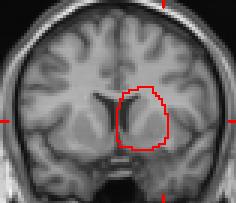
Current mask restricts VOI: This is a handy feature. The idea is to define a tissue type you want to include, such as grey matter (GM), and then be able to draw a quick and sloppy ROI around a grey matter structure (e.g. amygdala) without worrying too much about accurate drawing. When a ROI is drawn, all non-GM voxels are removed from the ROI (see example in figure below). The associated Help button provides instructions for use. It is particularly handy to use the HistoTool to define a tissue type, then use the resulting mask to constrain subsequent VOIs.
 |
 |
This pair of images illustrates BrainMaker's mask exclusion feature, where a predefined mask limits the pixel values which are accepted into a ROI. A large and sloppy ROI was drawn as shown in the far left image. With the "mask restriction" mode enabled using a GM mask, the grey-matter pixels are the only ones that are included in the resulting ROI; white matter and CSF have been excluded. This feature can drastically reduce the amount of time spent drawing many types of VOIs. |
Write mask: Writes the current working VOI mask to a 3D image file. Non-mask pixels are set to zero, while masked pixels have a value of 1. The actual value of the masked pixels can be changed to another integer value if desired.
BrainMaker Components:
BrainMaker is written as an IDL Object, called "ViewVol". It is designed to be used as either a standalone program, as in BrainMaker, but it could also be incorporated as a modular unit of another uber-program. The 3 Views are actually instances of the same underlying object "ViewSlice". Most of the functionality of BrainMaker is contained within the ViewSlice objects, such as drawing, display, overlay, color tables, connected pixel search, etc. ViewVol is responsible for coordinating between the several ViewSlice instances. The Alt view is another ViewSlice which contains its own Options Menu, so the color table can be independent of the main image. Other IDL Objects used in BrainMaker include HistoTool, VOIGroup, and Undo. Each of the objects is designed to be plugged into other applications. Contact Terry if you have questions about how to use these objects in your own programming efforts!