This page contains a tutorial for Roger Woods' coregistration package, AIR. Some of the details are specific to the Keck Lab. The tutorial shows what you can expect by selecting different options and provides three examples of various types of coregistrations. For additional information, refer to the page of AIR links.
Table of Contents:
II. File Formats
A. AIR data types (8-bit, 16-bit)
B. Values in .hdr file
C. Data pre-processing
D. Cubic voxels
IV. Tutorial
A. GUIs
B. PET-to-PET (intersubject)
C. MRI-to-MRI (intersubject)
D. PET-to-MRI (intrasubject)
E. Multiple subjects (batching)
F. BrainSqueezer Demo
Coregistering one image to another has two distinct steps: (1) determining the spatial relationship of the object image to the target image, and (2) reslicing the object image to create a new image volume with features that (hopefully) are in the same location as corresponding features in the target image. The goal is to move the object image into the spatial coordinate system of the target image. These two steps can be performed independently, although step (1) must be performed first.
In step (1), the align step, the object image is compared to the target image using some criteria such as minimization of the difference (or ratio) of the two images. The object image is iteratively moved in space and compared to the target image, and when the difference is small enough the current movement parameters are saved in a ".air" file. The ".air" file contains a 4x4 transformation matrix which specifies the [x, y, z] transform, the [yaw, pitch, roll] rotation, the [x, y, z] zoom, and perhaps other higher-order parameters that allow more localized transforms.
Step (2), the reslice step, applies the transform parameters in the ".air" file to the object file, creating a new file containing the coregistered (resliced) object file, which now should correspond spatially to the target file.
The accuracy of the coregistration depends upon many factors, most of which are related to determining the transform parameters. The reslice step can affect the level of apparent smoothing, depending on the interpolation method used, but does not have much effect on the overall accuracy.
AIR is primarily a command-line program. Although there are helpful GUIs (see below), you will need to type commands in order to take full advantage of AIR's capabilities. AIR is currently compiled at the Keck Lab to run on both SUN and linux platforms. You can play with AIR and try to coregister any of the files in the directory:
| /study/training/AIR_coreg/ | ||
Since AIR is a command-line program, you will (hopefully) soon come to the conclusion that typing in parameters and waiting several minutes for a response is all there is to it. To get the full measure of enjoyment from this excercise, you will probably want to see the reulting images. SPAMALIZE's BrainSqueezer is a good program to use for this, especially if your Object and Target images have different dimensions. AFNI is another good option.
For really spectacular results, use AIR's "warp" programs. These are similar to "alignlinear" and other standard AIR programs, but use many more parameters (up to 168!). You should only need the "warp" programs if you are fitting one high-resolution MRI to another from a different person. The "warp" programs are not explained in this tutorial, but once you get the hang of the regular AIR programs you will be able to use the "warp" programs as well.
A. AIR data types (8-bit, 16-bit)
There is an in-depth discussion of file formats on the AIR homepage. Familiarity with this material will be assumed for the following discussion.
AIR uses the ANALYZE 7.5 file-format. This is an older but still useful format, consisting of a ".img" file containing the image data, and a small ".hdr" file containing information such as the [x, y, z] dimensions, the pixel dimensions (in mm), the bits/pixel, and the global min/max. AIR can deal with either 8 bits/pixel or 16 bits/pixel. 8-bit data has values ranging from 0-255 (256 = 2^8) and is much simpler from AIR's point of view. 16-bit data has values that range from 0-65535 (65536 = 2^16), or can also have negative and positive values that range from -32768-32767.
The data are stored in the ANALYZE file in one of these integer-only formats. A scaling factor can convert the integer values to any range of floating-point values. Unfortunately, AIR does not make use of the scaling factor utilized by SPM and SPAMALIZE to convert from computer-format integers to "real-data" values. This is actually not too important if you are using AIR to coregister one MRI scan to another, since the MRI scans are essentially unscaled. However, if you plan to coregister quantitative PET data, or any series of fMRI or PET data that has been created using SPM or SPAMALIZE, you will have to figure out how to approach the issue of determining the correct scale factor. Ask Terry Oakes if you have any questions about this.
There are 4 different versions of AIR, one for each data type you are likely to encounter:
- 8 bit (0-255)
- 16 bit type 1 (0-65535)
- 16 bit type 2 (0-32767)
- 16 bit type 3 (-32768 - +32767)
It is crucial that you select the appropriate version for your data. Any version can read any type of data, but a particular version can only write data in its own format. As a general guideline, refer to the following table:
| Data Type | Typical Range | AIR version | Comments |
| PET raw | -32k - +32k | 16 bit type 3 | Avoid coregistering raw data! |
| PET quantitated | -32k - +32k | 16 bit type 3 | PET data can contain negative values. |
| PET quant. FDG | 0 - +32k | 16 bit type 2 | Should contain no negative values. |
| PET (old) | 0-255 | 8 bit | 8 bit data can reduce precision- avoid if possible. |
| MRI (raw) | 0-32k | 16 bit type 2 | Should contain no negative values. |
| MRI (byte-scaled) | 0-255 | 8 bit | Good for most imaging and coregistration tasks. |
| fMRI | 0-32k | 16 bit type 2 | Should contain no negative values. |
As you can see, there will be times when you will be using different types of data. For instance, you will eventually want to coregister a quantitated PET data set to a MRI volume. The various 16-bit types are interchangeable for the purposes of reading by AIR, but not so when writing. Thus, you should choose the AIR version based on the type of files you wish to write. In this example, you should choose the 16-bit type 3 version, since you will want to write the resliced PET data with the same scale as the original quantitated PET image.
At the Keck Lab and the LfAN, you can select which version of AIR to run by running the script "pickair":
| lan175%pickair Welcome to pickair! Please choose a version of AIR to use (A-C are latest): A AIR 3.0, 16 bit/local/apps/AIR3/16_bit B AIR 3.0, 16 bit II/local/apps/AIR3/16_bit_type2 C AIR 3.0, 8 bit/local/apps/AIR3/8_bit 1 AIR 3.0, 16 bit/d4/opt/AIR3/16_bit 2 AIR 3.0, 16 bit II/d4/opt/AIR3/16_bit_type2 3 AIR 3.0, 8 bit/d4/opt/AIR3/8_bit 4 Thor AIR 3.0 8 bit/thor/AIR/AIR3.0 5 Thor AIR 3.07 8 bit/thor/AIR/AIR3.07 6 01/1994 8 bit/gig/AIR/compiled8bit 7 01/1994 16 bit/gig/AIR/compiled16bit Please enter A - 7: 1 Enter 'y' if you would like this selection to be permanent, or anything else to just use this choice once. You can change your permanent choice by running 'pickair'. A file called '.airpath' will be created in your home directory. Always use this version of AIR: y |
|||
This script is not used much anymore- it was more useful before AIR acquired the ability to detect if byte-swapping was needed. It is a somewhat intrusive program, and can make scripting difficult. Most of our data are of "type 2", meaning the data range from 0-32k. In general, you should try to avoid using pickair. If you are using it, you should use options 1, 2, or 3 unless you are trying to replicate an old study which used one of the other (older) versions of AIR. The plain "16 bit" option refers to "16 bit type 1". You can check the .hdr values by using "scanheader":
| lan175% scanheader PET_1686.hdr Welcome to AIR application scanheader Using AIR 3.0, 16 bit = /d4/opt/AIR3/16_bit Run 'pickair' to change this. bits/pixel=16 x_dim=128 y_dim=128 z_dim=35 x_size=1.875000e+00 y_size=1.875000e+00 z_size=4.250000e+00 global maximum=32767 global minimum=0 |
|||
Alternately, you can insert the full path and program name into your call. For instance, you could try:
/apps/AIR/AIR5.05/16bit_type2_linux/alignlinear filename param1 param2 etc.
The latest version of AIR (AIR v. 5.05) can automatically detect if a file needs to be swapped, e.g. if a file was created on a SUN (big-endian) but you are working on a linux (little-endian) machine. AIR doea this by examining the .hdr file, where the first value should be "348". If this is not true, AIR assumes this is because the data need to be swapped, in both the .hdr file and in the image file. Usually this works seamlessly. One thing that can throw a wrench into the works is if you have some data that you convert to ANALYZE format by renaming a block of data (e.g. an AFNI BRICK) from "filename.BRICK" to "filename.img", and then take a .hdr file and modify it to correspond to the data of interest. So far so good, but what can happen is that the data may have been created using a SUN, and if you are working on a linux box when you create the .hdr file then the .hdr file will always be read swapped correctly but the data will never be correctly swapped, by either a SUN or a linux box.. If this happens, the solution is to explicitly swap one or the other of the files, using e.g. the swap utility in Spamalize.
AIR only uses a small number of the fields in the ANALYZE-format .hdr file. However, all of the fields it does use must be present (and accurate) in order for AIR to work properly. Most image-processing programs that claim to write an ANALYZE-formatted file do not fill in all of the parameters in the .hdr file, or else fill them incorrectly. As far as I am aware, SPAMALIZE writes a correct ANALYZE .hdr file with respect to values needed by AIR, SPM, and SPAMALIZE. AIR writes a minimal .hdr- it leaves most values blank. SPM99 writes ANALYZE files that are readable by AIR, but the scaling factor used by SPM99 will be lost in the output (resliced) image. Following are the only parameters that AIR uses:
| name | units | range |
| bits/pixel | - | 8 or 16 |
| x dimension | pixels | 1-256+ |
| y dimension | pixels | 1-256 |
| z dimension | pixels | 1-256+ |
| x pixel dim | mm | 0.5-10.0+ |
| y pixel dim | mm | 0.5-10.0+ |
| z pixel dim | mm | 0.5-10.0+ |
| global min | integer | -32768 or 0 |
| global max | integer | 0 or 32767 |
You must ensure that these values are correct for any data that you feed into AIR. This is particularly important for MRI and fMRI data, since most of the programs we use to create ANALYZE files from the raw MRI/fMRI data don't know how to extract the pixel dimensions from the raw data. There is a program supplied with the AIR package called "makeaheader" that lets you create a new .hdr file. Another approach is to use SPAMALIZE's "File ->Fix header -> ANALYZE" program, which provides a simple GUI where you can fill in the values.
If you are familiar with SPM's usage of ANALYZE files, you may have noticed that AIR does not pay any attention to the "Calibration Factor" stored in the "funused1" field of the .hdr file. This means that if you use AIR to coregister an ANALYZE file created with SPM or SPAMALIZE, the new file will not contain the scale factor. If you want to use the scale factor (for e.g. quantitated PET data, some fMRI data) you will need to figure out what it is for each file.
The range of values in Table 2 for the pixel dimensions is approximate. Actually, you can have any floating point value, but only positive values make sense, and you should be suspicious of values that fall outside of the suggested range.
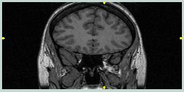
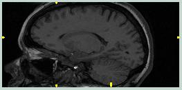
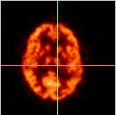
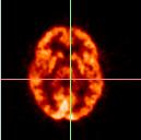
The goal in pre-processing data for input to AIR is to maximize the likelihood that AIR will try to match pixels from regions that are important. A MRI scan contains information not only from the brain, but also from the skull, scalp, neck, eyes, etc. A PET scan usually contains information primarily from the brain, with the skull being devoid of signal and the skin, eyes, etc. having a relatively small signal. The goal is usually to match one brain to another, so matching the skull, etc.should be avoided since this can skew the results for the brain. Thus, it is usually a good idea to strip the skull and scalp in a MRI scan away from the brain, leaving a 3D image volume containing only brain tissue.
|
|
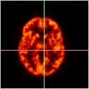
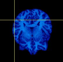
The images to the left show the coronal and sagittal views of MRI scan 1866. Note the large amount of non-brain tissue. Also, notice how the highest data values (brightest pixels) are non-brain. | ||
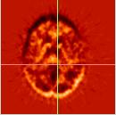
|
|
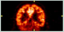
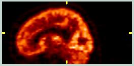
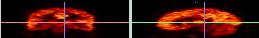
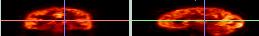
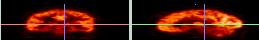
These images show coronal and sagittal slices from a FDG PET scan. The signal from non-brain tissue is minimal, the pixel value distribution is quite different from the MRI images, and the Field-of-View (FOV) is different. | ||
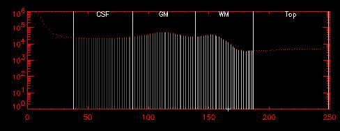
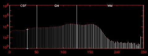
Most of the MRI data we acquire benefits from "lopping" the highest data points. These values correspond to regions containing large blood volumes, fat, and other non-brain tissue. These values tend to occupy a large fraction of the "bandwidth" or allowable data values, as shown in the following histogram:
 |
The values in the section labeled "Top" correspond to non-brain tissue. Note that, on this log-based y-axis, these pixels constitute less than 1% of all pixels. The "WM" section shows values that are generally white matter; "CSF" shows CSF values, and the unlabeled section between them shows grey-matter values. | ||
If we "lop" these high values, or set all values above a certain value to that value, we can optimize the range of used values to reflect the pixels we are actually interested in. This is a crucial step if you want to convert your data to 8-bit format (0-255), which is useful for most MRI images. This is usually the first step in the pre-processing chain after reconstruction.
 |
The histogram above was "lopped", setting all values larger than 165 to be equal to 165. The resulting image volume was then scaled from 0-250 and converted to an 8-bit data set to reduce memory and storage requirements.
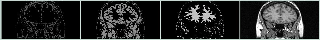
The CSF, GM, and WM regions can be more clearly seen now. The resulting tissue classifications are shown below. |
||||||||||
 |
|||||||||||
| CSF | GM | WM | Lopped image | ||||||||
Notice how the contrast within the brain is improved in the lopped image, compared to the coronal image at the top of this section. Also, nearly all of the scalp, cheeks, blood vessels, etc. have a uniform white color, since they have been set to the new highest value.
The next step is to strip away all non-brain tissue. This can be done using the SPAMALIZE BrainStripper program within BrainMaker. (For details, see the BrainMaker web-page.) SPM99 also has a skull-stripper that works fairly well, although both of these approaches may require some manual editing for showcase results. The idea is to define a Region-of-Interest (ROI) whose pixels overlay all brain tissue and enclosed CSF (ventricles), but exclude all non-brain tissue.
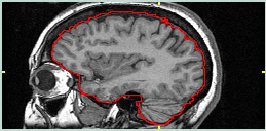 |
This image shows a sagittal view from the MRI data set with a ROI drawn around the brain. The goal is to include pixels from the brain, and perhaps additional pixels present in the other image volume for this object/target pair which are desirable references.
For PET/MRI, the blood vessel at the top of the brain should probably be included. For MRI/MRI it does not matter as long as both members of the pair are consistent. |
|||
 |
||||
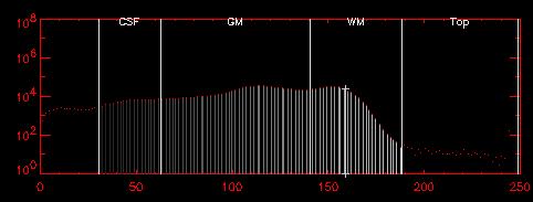
| The histogram to the left shows the pixel value distribution after "lopping" the original data and then stripping away all non-brain tissue. There is still a small fraction (<1%) of pixels with values larger than typical WM. These are due mostly to blood vessels within the brain. | ||||
After lopping the high values and stripping away non-brain tissue, the MRI data are ready to be fed into AIR.
Internally, AIR converts all of the image information to cubic voxels. A cubic voxel is simply a voxel with all three sides the same length (mm). If you feed AIR data with non-cubic voxels, AIR will internally interpolate and reslice to yield a new image volume (in memory only) with cubic voxels. Most of the image data we use has non-cubic voxels. You can request that AIR create a reslice file with either cubic voxels (the default) or standard voxels. A standard voxel is defined as a voxel having the same dimensions as the target image. You can also request voxels of any arbitrary size.
You will generally obtain the crispest (and fastest) results if you stick to cubic voxels.
Following is a list of the various commands available in the AIR package. These can be typed into the command-line or incorporated into a shell-script. I included a brief description after the programs I actually use regularly.
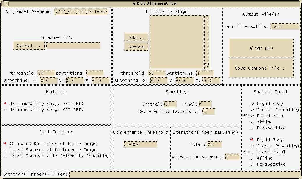
The most recent version of AIR has two Graphical User Interfaces (GUIs), one to aid in determining the alignment parameters (a.k.a. making the ".air" file), and another to aid in doing the reslicing (applying the ".air" file transform parameters). AIR is primarily a command-line oriented program, and these GUIs ultimately just create a command that is used to call AIR. However, the GUIs are very useful, especially for beginners.
The following image shows AIR's "align" GUI menu:
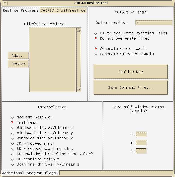
The following image shows AIR's "reslice" GUI menu:
Access these menus by typing:
| lan175% /d4/opt/AIR3/16_bit/align.tcl
lan175% /d4/opt/AIR3/16_bit/reslice.tcl |
|||
You should use the version of these GUIs that corresponds to the AIR version you specified in "pickair".
The first example is a simple PET-to-PET intersubject coregistration. I call this simple because the data do not need to be skull-stripped, and the two PET data sets are fairly similar in both spatial extent as well as pixel value distribution.
We will coregister the following files:
Target: /exp/training/AIR_coreg/PET_1866.img
Object: /exp/training/AIR_coreg/PET_1770.img
Using the "align" GUI, select PET_1866.img for the "standard" file (this is a.k.a. the target), under "Files to align", "Add" PET_1770.img, and select "Traditional". Then click "align now". This takes 15-ish minutes on lan175, and about 3 minutes on a fast (800 MHz) linux box. If you want to see what the actual command looks like, examine the command file
/exp/training/AIR_coreg/pet_to_pet/align_1770_trad.com
Using SPAMALIZE's BrainSqueezer, we can see how well we did. Following are pictures of the original data:
 |
 |
||||||
| Target images (PET_1866) | |||||||
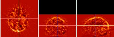
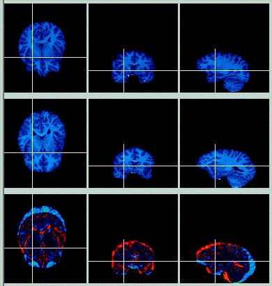
| The target image is shown in axial, coronal, and sagittal views in the top row. The object image is shown in the middle row. A difference image, obtained by subtracting one image from the other, is shown in the bottom row.
From the difference image, it can be seen that the object image is farther forward in the image frame than the target image. |
|||||||
 |
 |
||||||
| Object images (PET_1770) | |||||||
 |
 |
||||||
| Difference images (PET_1866 - PET_1770) | |||||||
Now look at the resliced image, using a traditional (9-parameter) fit.
 |
 |
||||
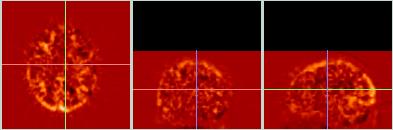
| The object image (PET_1770) has been coregistered using a traditional (9-parameter) fit and resliced using a trilinear interpolation scheme.
The difference images at the bottom (between the target and the resliced data) show a fairly good match, although the dark region at the lower left edge of the axial and coronal views indicates a small mismatch. |
|||||
| Resliced images (rPET_1770_trad_trilin) | |||||
 |
 |
||||
| Difference images. | |||||
To see if we can improve the fit, we will now try the alignment using an affine (12-parameter) fit.
 |
 |
||||
| The object image (PET_1770) has been coregistered using an affine (12-parameter) fit and resliced using a trilinear interpolation scheme.
The difference images at the bottom (between the target and the resliced data) show a better match than for the 9-parameter fit. This difference image looks noisier, indicating that there is less structure or signal due to the difference, so the target and resliced images are a better match. |
|||||
| Resliced images (rPET_1770_affine) | |||||
 |
 |
||||
| Difference Images | |||||
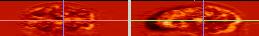
Now that we like the fit, let's see how a more sophisticated reslice interpolation scheme might improve things. The goal is to minimize interpolation errors, although the calculated fit will be the same. The tradeoff is in time: the trilinear interpolation takes about a minute on lan175 (a SUN Ultra2), whereas the more sophisticated "3D windowed sinc" takes much longer (2.5 hours!). Also, the sinc interpolation cannot yield an image volume with non-cubic voxels. For data with relatively low resolution such as PET and fMRI, there is no real benefit to using a sinc interpolation.
 |
The difference images for comparing the two types of reslice interpolation (trilinear and 3D sinc) show very little difference for these PET data.
Most of the apparent difference between these two difference images is because the sinc data (bottom) consists of smaller cubic voxels (1.85 mm^3), whereas the trilinear data (top) retains the larger pixel size (1.85 x1.85 x 4.25 mm) of the original data. Zooming the sinc-images to get the same size and aspect-ratio as the affine images leads to the apparent (but false) greater smoothnes in the sinc data. |
|||
| Difference (affine- target) |
||||
 |
||||
| Difference (sinc - target) |
||||
Here is an example of a Perl script I wrote that calls AIR to align two similar PET images:
| #!/usr/bin/perl -w # #Purpose: # Script to use AIR to coregister an image file to a single target file. # You must edit this file to change the name of the target file (line 16) # the object file (line 17), the output file (line 18), and the .air file (line 19). # You can also change the AIR thresholds (-t1, -t2) on line 31. #History: # 03-05-06 Written by Terry Oakes @ UW-Madison Keck Imaging Lab. use Cwd; $prog_str = " (air_run.pl)"; #!!!!!!!!!!!!!!!!!!!!!!!!!!!!!!!!!!!!!!!!!!!!!!!!!!!!!!!!!!!!!!!!!!!!! # Edit the following target and object file names: # $file_tgt = "/study/micropet/mask/avg_masked_GM.img"; $file_obj = "/study/micropet/mask/AV_coreg_masked_GM.img"; $file_out = "/study/micropet/mask/AV_coreg_masked_GM_new.img"; $file_air = "/study/micropet/mask/AV_coreg_masked_GM.air"; print "Starting AIR coregistration \n"; $air_dir = "/apps/AIR/AIR5.05/16_bit_type2_linux/"; $align = "$air_dir" . "alignlinear"; print "align command: $align\n"; $reslice = "$air_dir" . "reslice"; print "reslice command: $reslice\n"; print "Aligning $file_obj\n"; # Issue the align command: # |
||
Aligning one subject's anatomic (high-resolution) MRI scan to another subject's MRI scan is challanging. Since the resolution and detail is better than e.g. a PET or fMRI scan, it is much easier to see when specific anatomic structures are not properly aligned. As mentioned above, it is best to use a skull-stripped brain image to determine the reslice parameters (.air file). These parameters can later be applied to the original non-skull-stripped image data, if desired.
We will coregister the following files:
Target: /exp/training/AIR_coreg/mri_lop_masked.img
Object: /exp/training/AIR_coreg/mri_1770_lop_masked.img
These files have dimensions: [256 x 256 x 124], pixel dimensions: [0.9, 0.9, 1.1] mm. Since these files are much larger than the PET files, the coregistration takes longer; this MRI-to-MRI alignment took about 45-50 minutes on lan175, compared to 15 minutes for the [128x128x35] size PET data.
First, let's see what happens if we coregister an entire head, without stripping away the skull from either of the two MRI images. I used an affine (12-parameter) fit, with trilinear interpolation.
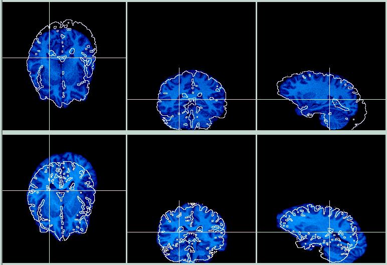
The top row is the target image, the bottom row is the (resliced) object image. The contour lines from the Target image are overlaid on the Object image, while the contour lines from the Object image are overlaid on the Target image. The results are OK, especially in the posterior area, where the shape of the skulls are similar. However, in the anterior portion of the brain the registration is poorer, because the fit is influenced by the eyes, skull, sinuses, nose, etc.
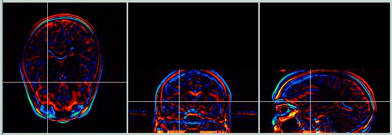
The subtraction images below (Target - Object) show areas where the images differ by a large amount. Yellow/red shows where the Target image has higher values, and green/blue shows where the Object image has higher values.
Now let's try using a set of skull-stripped images.
 |
|||
| The pictures to the left show the original skull-stripped images (Target on top row, Object on middle row, Difference image on bottom row). The difference image shows that while the two brains have a similar shape, they do not align in space very well; a transform in the y- and z-dimension will help this out.
The brains were skull-stripped using BrainMaker. The goal was to remove all non-brain tissue, and to leave a thin bit of CSF surrounding most of the brain. |
|||
At first blush, using a skull-stripped brain image could present its own set of problems, since AIR might lend too much credence to the boundary drawn between the masked image data and the empty void. However, by using an appropriate value for the threshold within AIR, most of the boundary pixels are actually ignored. AIR does not consider values less than the desired threshold (which in this case was 55) when computing the cost function value, so these lower values do not influence the result.
 |
 |
||
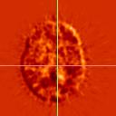
| The pixel values near the edge of the brain are typically less than 50, for an 8-bit image volume scaled from 0-255. In the histogram above, the "CSF" region shows these pixels. For example, the pixel under the crosshairs has a value of 33, as shown in the histogram (vertical line with plus-signs on either end). | |||
Since the edge pixels are ignored, a "soft" edge is the effective result, with the actual location of the ROI within the CSF not influencing the final result. Instead, the actual edge of the brain foms the boundary in most regions, so AIR only considers voxels within the brain.
Hmmm. The images below show the result of aligning the two skull-stripped brains, and reslicing the skull-stripped Object image according to the parameters in the .air file. The skull-stripped Target image is on the top row, the resliced skull-stripped Object is on the bottom row, and the contours have been exchanged. This is clearly a coregistration gone awry.
 |
I show these images for two reasons: (1) I only finished this coregistration a couple of hours before the lecture I gave on AIR, and (2) this is an excellent example of AIR failing to work for no apparent reason, and emphasizes the need to carefully check every result produced by AIR. Or any other coregistration program, for that matter. Of course, there is always a reason why it didn't work, but often finding the reason is more work than most folks have time for.
Let's pretend that the coregistration worked (!) and that we like the result (!!). We might want to see the original non-skull-stripped image registered to the non-stripped target for some reason. By altering the .air file, we can reslice the original (non-skull-stripped) image, using the parameters (.air file) calculated for the skull-stripped image.
| /d4/opt/AIR3/16_bit/alignlinear /da/exp/training/AIR_coreg/mri_lop /da/exp/training/AIR_coreg/mri_1770_lop_masked /da/exp/training/AIR_coreg/mri_2_mri/mri_1770_lop_masked.air -m 12 -t1 55 -t2 55 -b1 0.0 0.0 0.0 -b2 0.0 0.0 0.0 -p1 1 -p2 1 -x 1 -s 81 1 3 -r 25 -h 5 -c .00001 |
This command tells AIR to find a transform to align the Object image (mri_1770_lop_masked) with the Target image (mri_lop) using an affine (12-parameter) fit. | ||||||
| /d4/opt/AIR3/16_bit/reslice /da/exp/training/AIR_coreg/mri_2_mri/mri_1770_lop.air /da/exp/training/AIR_coreg/mri_2_mri/rmri_1770_lop_masked -n 1 -k |
This command tells AIR to reslice the Object file specifiied in the .air file, and to put the result into a new file, named "rmri_1770_lop_masked.img" | ||||||
| Although the AIR file contains some recognizable text characters, it is not primarily a text file, and it should be altered by using the AIR command "mv_air", which changes the reslice file specified in the .air file. The new Object file must have the same dimensions as the original. | |||||||
| /d4/opt/AIR3/16_bit/mv_air /da/exp/training/AIR_coreg/mri_2_mri/mri_1770_lop.air /da/exp/training/AIR_coreg/mri_1770_lop |
This command will substitute a new Object file into the .air file, keeping the same transform matrix. | ||||||
Aligning one modality (such as PET) to another (such as MRI) is also a challenging task for a coregistration program. There are three things that make this a difficult task:
AIR uses a more sophisticated approach for inter-modality registration. Also, it is more important to use a skull-stripped MRI image, containing only the brain tissue. The following example uses the files:
Target: /exp/training/AIR_coreg/mri_lop_masked_flip.img
Object: /exp/training/AIR_coreg/PET_1866.img
A PET image is coregistered to a MRI image from the same subject. A traditional (9-parameter) fit was used, and the PET data were converted to have the same number of pixels (and pixel dimensions) as the MRI data.
The actual command files used to perform the alignment and reslicing are:
| /d4/opt/AIR3/16_bit/alignlinear /da/exp/training/AIR_coreg/mri_lop_masked_flip /da/exp/training/AIR_coreg/PET_1866 /da/exp/training/AIR_coreg/pet_2_mri/PET_1866_2_mri_flip.air -m 9 -t1 55 -t2 55 -b1 0.0 0.0 0.0 -b2 0.0 0.0 0.0 -p1 256 -p2 0 -x 1 -s 81 1 3 -r 25 -h 5 -c .00001 |
The align command (top) calls the 16-bit type 1 version of AIR, and specifies the target file (MRI), object file (PET), name of output .air file, a 9-parameter alignment, and other standard parameters.
The reslice command (bottom) specifies the 16-bit type version of AIR, the .air file with the transformation parameters, and the name of the output .img file. |
|||
| /d4/opt/AIR3/16_bit/reslice /da/exp/training/AIR_coreg/pet_2_mri/PET_1866_2_mri_flip.air /da/exp/training/AIR_coreg/pet_2_mri/rPET_1866_to_mri_trad -n 1 -k |
||||
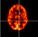
The following set of images shows how well the coregistration worked:
 |
||
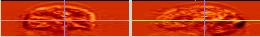
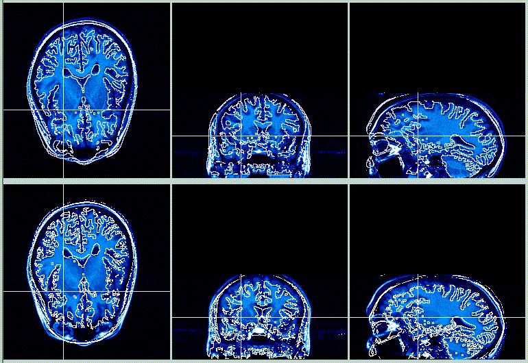
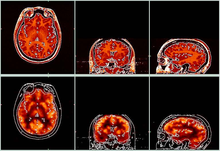
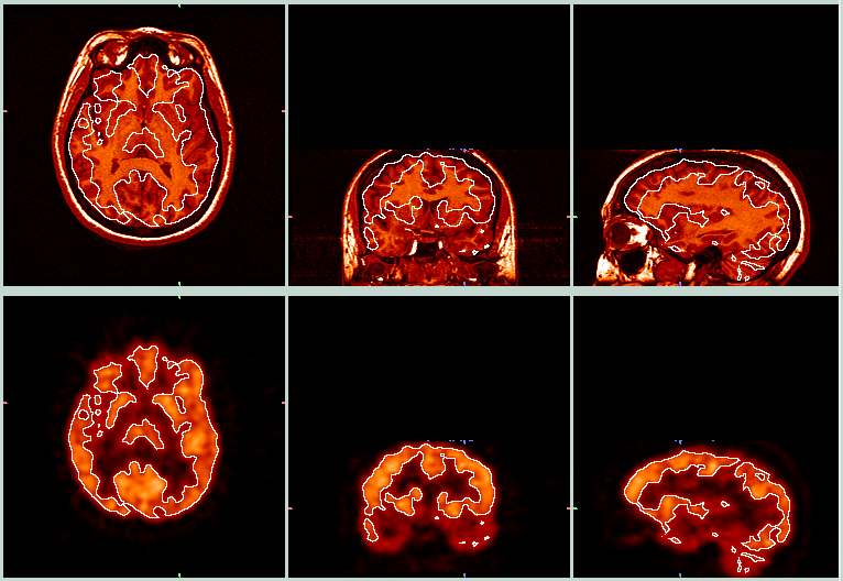
| The picture above shows the target MRI (top row) and the resliced PET (bottom row). The white lines were derived from the edges of the MRI images, and were then overlayed onto the PET image so you can see how well the the alignment worked. This alignment appears to have worked pretty well. These images were made with BrainSqueezer. | ||
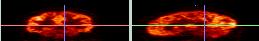
 |
||
| This is a similar view as the previous picture, with the MRI (top row) and resliced PET (bottom row). Here, the white outlines were derived from the PET images and overlayed onto the MRI images. Note how the outlines of the brighter regions in the PET data correspond closely with the GM/WM boundaries in the MRI data. | ||
E. Multiple Subjects (batching)
With AIR it is easy to write scripts to coregister a series of images. Following is a Perl script I wrote to coregister all ANALYZE files in the current directory to a single image, and then to reslice each object-image to yield a coregisterd image. You must run this script from within the directory where the files you want to coregister are contained. This is an example; you will have to make a few changes to run it with your data.
| #!/usr/bin/perl -w # #Purpose: # Script to use AIR to coregister a series of image files to a single target file. # All of the .img files in the current directory (where you are when you # call this program) are coregistered, in series, to a target file. # You must edit this file to change the name of the target file (line 17). # You can also change the AIR thresholds (-t1, -t2) on line 52. # # Either nearest-neighbor or sinc interpolation may be used for the reslice. # Use nearest-neighbor for initial testing, and use sinc for the final run. # Comment out one of lines 64 or 65. #History: # 03-05-06 Written by Terry Oakes @ UW-Madison Keck Imaging Lab. use Cwd; |
||
You should examine your image data to see where to set the threshold for the reslice operation, and change the values in the script accordingly.
BrainSqueezer is a SPAMALIZE program that substitutes the AIR "align" step with a manual, user-driven "by-eye" approach to determining the transformation matrix. Once a suitable transformation matrix is known, it is used as an input to AIR's reslice. Most of the images on this page were made using BrainSqueezer. Click the link to see the Brainsqueezer demo.
Following are some tips for using and troubleshooting AIR.